For the 1996 model year, GM replaced the tach-less Caprice digital instrument cluster with an analog cluster with a tachometer. In their infinite wisdom, the bean-counters at GM decided to eliminate other important gauges. DOH!
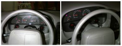
I did the gauge install in my 1996 Impala SS over the 1996 July 4th weekend. I now have a working set of gauges to monitor oil pressure and transmission/engine oil temperature. The red LED digital (Cyberdyne) gauges are almost unnoticeable when off, and very impressive looking when on, especially at night with my LT1 ScanMaster mounted on the steering column:
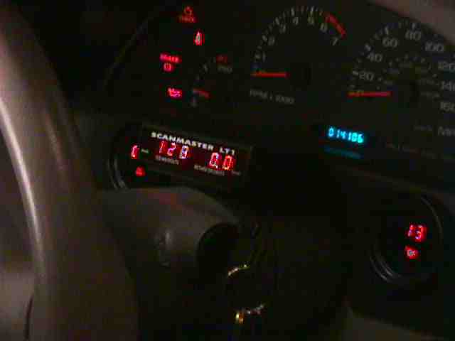
I worked very hard to make the install look factory. They are located in the black trim bezel just below the instrument cluster (ala Scott Mueller & Calloway). The oil pressure gauge is on the right and the temperature gauge is on the left, with trans or oil selected by a black mini rocker switch located below the gauge. The only cutting I had to do was in the trim piece which only cost around $15. I have the original trim piece, along with a set of hub caps, a spare console, body emblems and other assorted posterity parts in a box labeled "spare impala" in the basement.
Below is a detailed description of the way I installed the gauges shown above. I originally got the idea from Scott Mueller, the bow-tied guru, who did essentially the same thing long ago. The only difference is that Scott needed a tach (for his '94) and I needed an oil pressure gauge. Why didn't the General just put them all in to begin with? GO FIGURE! Here's how I did the install:
The gauges go into the black trim bezel equidistant from either end. Use a 2" hole saw and a file to get them to fit. Use a heated utility knife to cut a rectangular 5/8" x 3/8" hole in the bezel low and near the steering column (just behind the tilt lever) for the mini toggle switch that selects for transmission fluid or engine oil temperature function on the gauge. I had to slightly trim the lower dash where the bezel snaps in to provide clearance for the bottom of the gauges. Although this is completely hidden when the bezel is in place, I spent some time locating the holes for the gauges so as to minimize the dash trimming required. Next, fit the gauge leads to the six terminal pin connector, crimping and soldering each pin.
Raise the front of the vehicle and secure with jack stands. Drain the oil and remove the oil filter. Disconnect the fore and aft O2 sensor electrical connectors on the left catalytic converter. Be careful not to break the slender piece of plastic that attaches the connector to its mounting pin. I broke both of mine before I noticed that the coupled connector can be slid off its mounting pin before disconnecting. Use a 15mm deep well socket and a long extension to remove the cat. This makes for plenty of room to do the rest of the operation.
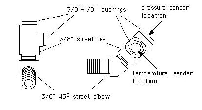
Originally, the oil pressure and temperature sender were mounted into a brass fitting attached to the 3/8" NPT tap located in the side of the oil filter adapter just above the oil filter (thanks to Scott Mueller for this idea). To remove the factory plug from the side of the filter adapter , you will need a 5/16" (8mm) square drive bit. I could not find such a tool at the local auto parts store, so I fabricated one out of a 1/2" soft steel rod which I ground down and then heat tempered. The brass fitting which screws into the tap was constructed out of a 3/8" 45 degree street elbow, a street tee and two 3/8"-to-1/8" bushings. The elbow is necessary to angle the senders up and away from the cat when it is in place. A sketch of the fitting best describes this setup. Construct the fitting as shown and install the senders as per the manufacturers instructions. Cut the leads to the same length and fit with a four terminal pin connector. Wrap the wires with plastic wire loom and then in stainless steel tape to protect them from heat. Screw this assembly into the tap. When properly positioned, the temperature sender should be pointing toward the front of the car and the oil pressure sender should point upward at a 45 degree angle. Finally, make a heat shield to encase the fitting and senders with stainless steel tape and fiberglass cloth. This shield looks very much like the factory heat shield surrounding the forward O2 sensor connector attached to the block.
The transmission temperature sender simply went into the line pressure tap on the left side of the transmission case. I talked this over with Ken Sundquist and his friends at Precision Performance. The sender in this location will see greater temperature fluctuations than if it was located in the pan. The advantages of putting it where I did are: 1) no drilling/tapping required and 2) I will be able to monitor trans temperature extremes in this location. Before installing the sender, fit the leads with a three terminal pin connector and cover them with wire loom. Pass the leads and connector under the floor pan heat shield until the connector protrudes out next to the frame.
Construct a wiring harness with the wires Cyberdyne supplied and the appropriate socket connectors to mate with the senders. Run this harness up around the the back side of the engine compartment under the master cylinder to the rubber grommet that passes the factory harness through the firewall next to the left fender. To get the wires through the grommet, first free the pinned loop of factory cable under the grommet from inside the engine compartment. Next, remove the 2 7mm screws holding the relay housing to the floor pan (behind the brake pedal) and push the housing to the side. Pull the rubber grommet into the car and remove the electrical tape sealing the factory harness. Push/pull the new harness through (I ran an extra capped wire for future use since this step was such a bitch), retape and push the grommet back into place. Repin the factory harness. Hard to tell it's not factory!
For power, I tapped into the cruise control fuse (#16) and for the dimming function, I tapped into the parking lamp fuse (#41). I joined these two wires with my harness and fished it up through the gap between the steering column and the instrument cluster. Here, I crimped and soldered the 6 terminal socket connector to mate with the gauges.
Reinstall the catalytic converter. Tighten the exhaust manifold flange bolts to 38 lb-ft and the exhaust pipe bolts to 15 lb-ft. Install a new oil filter and fill the crankcase with oil. Don't forget to reset the oil life monitor (key to ON position, depress the gas pedal fully and release three times within 5 seconds).
Previously, I had constructed a pretty large and nasty fitting out of brass adapters (described above) to accomodate both of the senders in the 3/8 hole in the oil filter adapter. The biggest problem with this arrangement was that the temperature sender was well removed from the oil stream and did not give an accurate reflection of the actual oil temps.
I have since eliminated this fitting and placed the temp sender into the hole using just a 1/4-3/8 brass bushing. Now the tip of the sender is directly in the flow of oil. I am using the SEO oil pressure sender to drive the Cyberdyne OP gauge and it seems to work fine. The resistance range is similar to that of the Cyberdyne sender. I ran a wire directly from the tan wire in the lower pass side kick panel to the gauge in order to bypass the infamous 68 ohm resistor.
Before I made this change, my oil temp guage would generally read right about the same as the coolant temps (read from the PCM) and almost never higher. Now, once the car is warmed up, the engine oil is 15-25 hotter than the coolant. I am running the 160 thermostat and my coolant temps at the PCM sender are about 173 at steady highway cruise and the engine oil is around 195. The other nice thing is that the temp changes are much more responsive to load in a predictable way. So far, the hottest I have seen my engine oil is 205 degrees.
From the drawings in the FSM, I can guess that the hole in the side of the oil filter adapter is closest to the line that sends oil out to the radiator for cooling and is therefore the "hot side" of the system. If this is the case, it seems that the stock oil-to-water cooler is doing an adequate job without cooling the oil too much. To the best of my knowledge, the oil should frequently reach a minimum of 200 degrees in order to burn off accumulated moisture and other volatiles. IMO, this is something to consider before adding additonal cooling capacity to a normally driven/occasionally abused street car. On the other hand, if you are going to be racing alot or just sitting and idling for hours, you may need something like the SEO oil-to-air cooler.
Parts list:
Black trim piece (bezel) World Parts:
GM part # 10250238 $15.27
Gauges (JC Whitney):
Cyberdyne 2-1/16" digital oil pressure gauge JCW p/n12BZ8988 $32.36
Cyberdyne 2-1/16" digital oil temperature gauge JCW p/n13BZ3960 $32.36
Cyberdyne temperature sender JCW p/n12BZ8991 $13.46 (2 required)
Cyberdyne oil pressure sender JCW p/n12BZ8992 $19.76
Brass NPT fittings (Local auto parts or plumbing supply store):
3/8" 45 degree street elbow
3/8" street tee
3/8"-to-1/8" bushings (2 required)
about $14 total
Electrical parts (Digikey):
SPDT Rocker Switch p/n SW303-ND $1.19
Pin connectors
1 6-circuit p/n A1412-ND $0.36
1 4-circuit p/n A1402-ND $0.34
1 3-circuit p/n A1400-ND $0.24
30 AWG tin pins p/n A1422-ND $4.44
Socket connectors
1 6-circuit p/n A1413-ND $0.43
1 4-circuit p/n A1431-ND $0.29
1 3-circuit p/n A1401-ND $0.32
30 AWG tin sockets p/n A1423-ND $4.44
Miscellaneous parts/tools:
5/16" (8mm?) square drive bit (I had to make one)
electrical tape
stainless steel tape
Fiberglass cloth
If you have questions or comments about this article send them to: Mike
© 1995